Post by Hawkeye on Apr 2, 2013 18:50:41 GMT -6
This is what I promised Wingover or anybody else who has this model of CH joystick. Apologies for the blurriness of some of the images, I had to get my son to snap some of them and I don't think he waited for proper auto-focus.
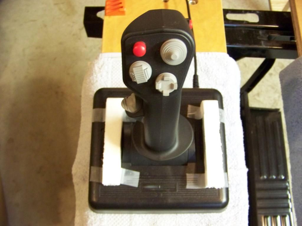
1) It is optional but you can tape some blocks of some material to the top side of the stick (I used Styrofoam) in order to protect the trim wheels and yoke parts while the stick is upside-down.
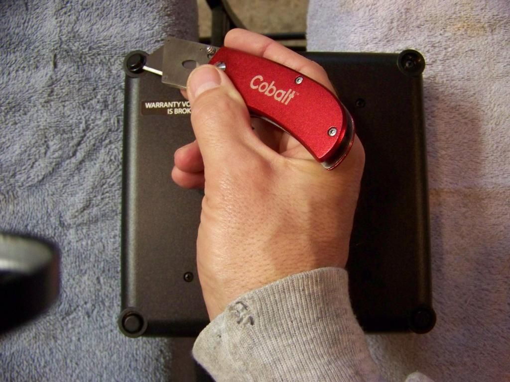
2) There are 8 screws holding the bottom cover on that must be removed. Warning: removing these screws VOIDS any warranty that may still be in effect for your joystick. Remove the 4 in the center of the stick, one of which is under the "void warranty" sticker. Then carefully peel off the 4 silicone feet of the joystick to access the other 4, set the feet aside in a clean location for later re-installation, and remove the last 4 screws.
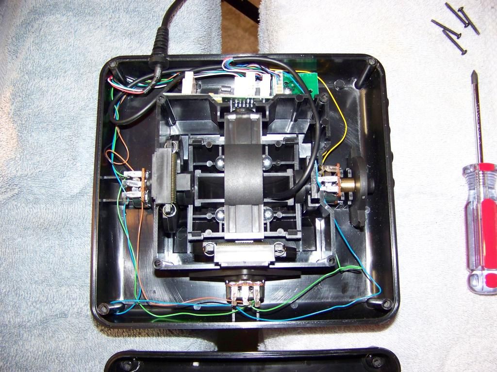
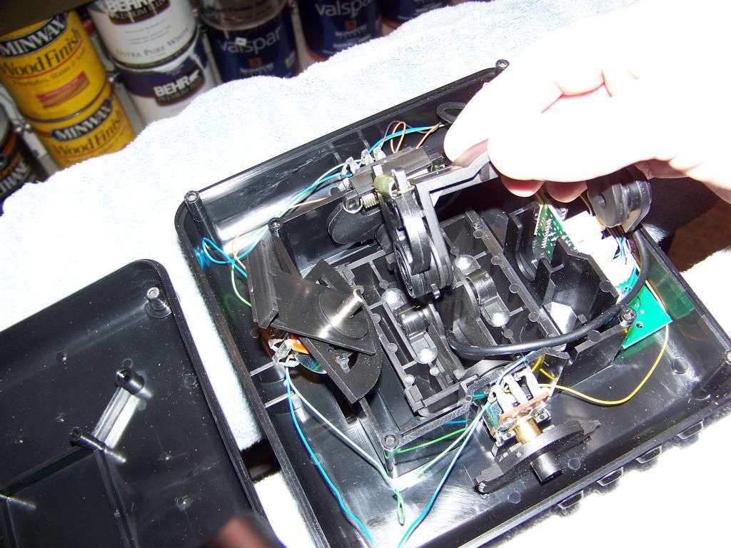
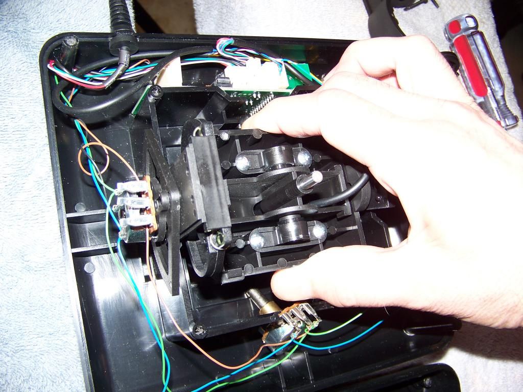
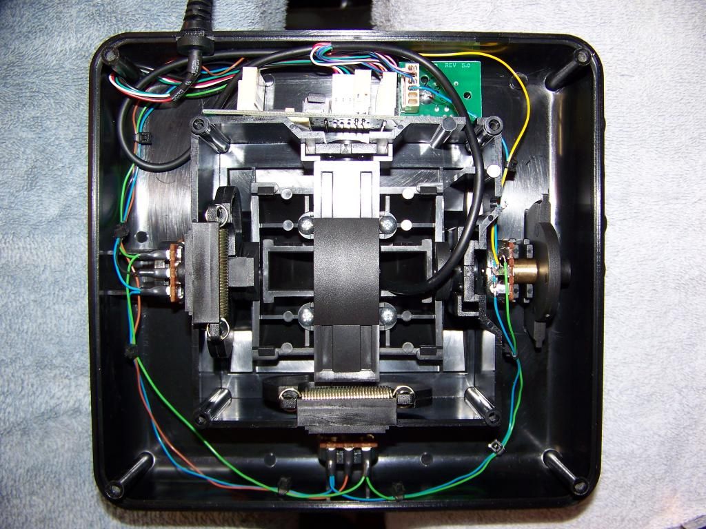
3) The open view. Pitch (Y) pot on the left, Roll (X) pot on the bottom, Throttle pot on the right. Note the chintzy "Sta-Con" type connectors on all the pots as original equipment. A couple of these were extremely loose on my unit, with one being on the left-most connection of the Roll pot. I suspect it was the problem, since testing of the original pots showed no discernable problem.
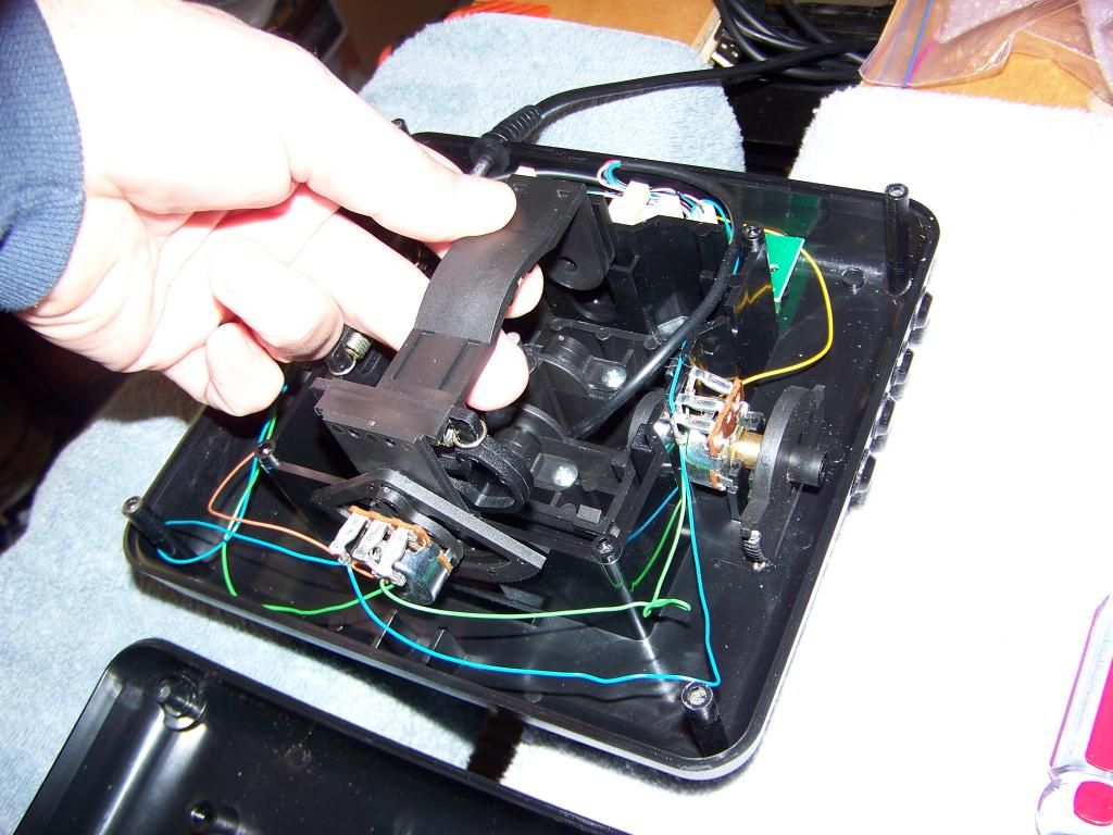
4) Lift the entire Roll yoke assembly straight up by lifting on both sides simultaneously. It is a friction fit. Note how the rod on the bottom of the stick unit engages the slot on the underside of the yoke. Also note that the front bearing slides into it's slot with the ROUND SIDE DOWN.
5) The trim wheel comes out with it.
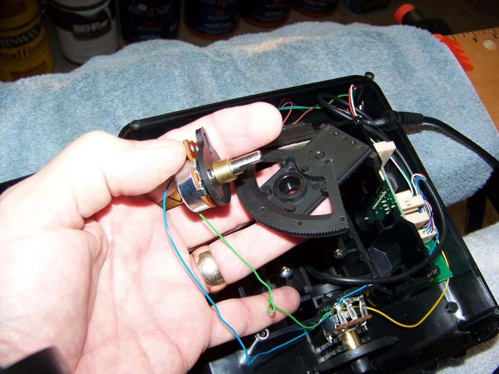
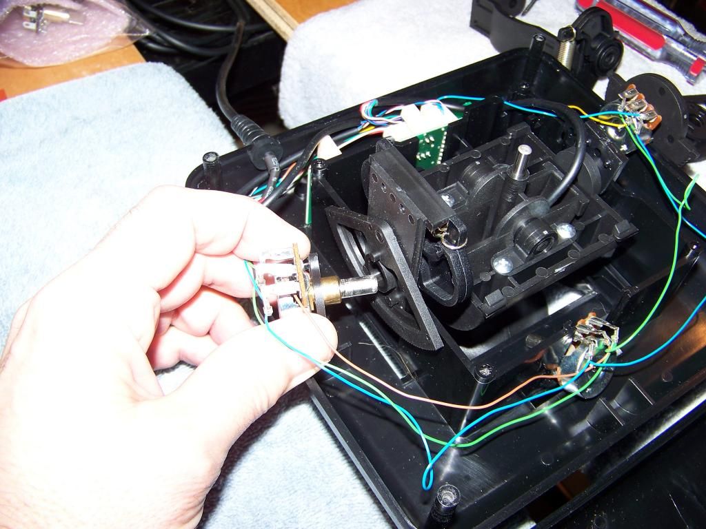
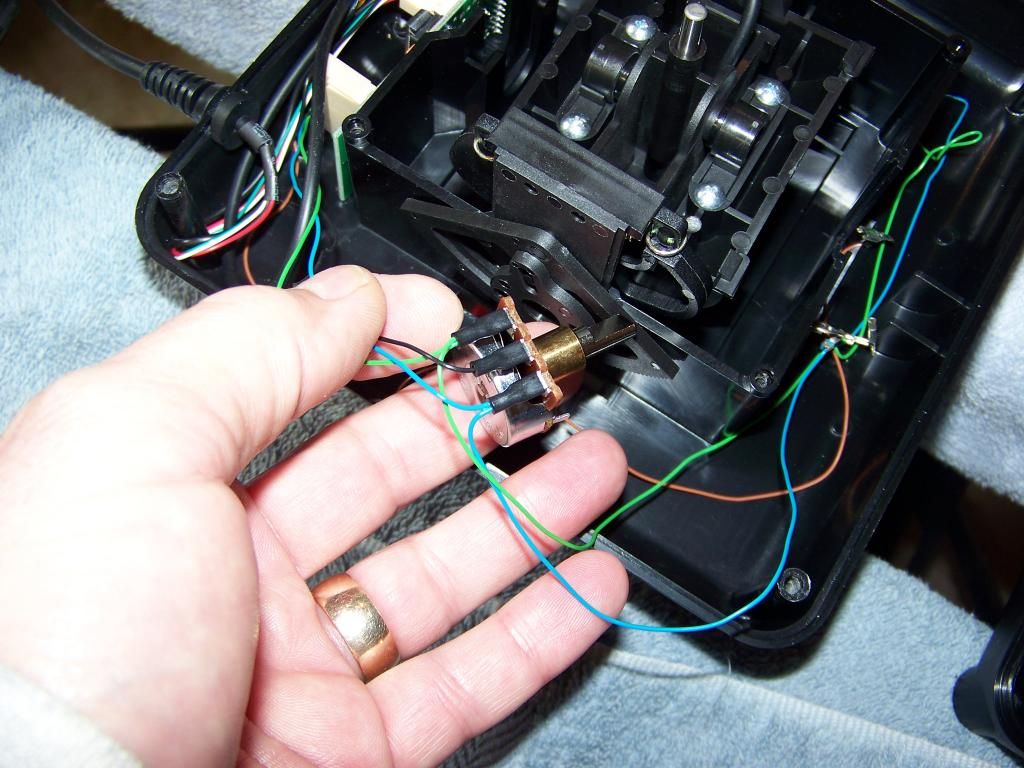
6) Pull the Roll pot and trim wheel assembly out of the end of the Roll yoke.
7) Pull the pot assembly off of the trim wheel unit. Note how the slot on the pot assembly fits into the trim wheel unit. It is not necessary to disassemble the trim wheel unit any further.
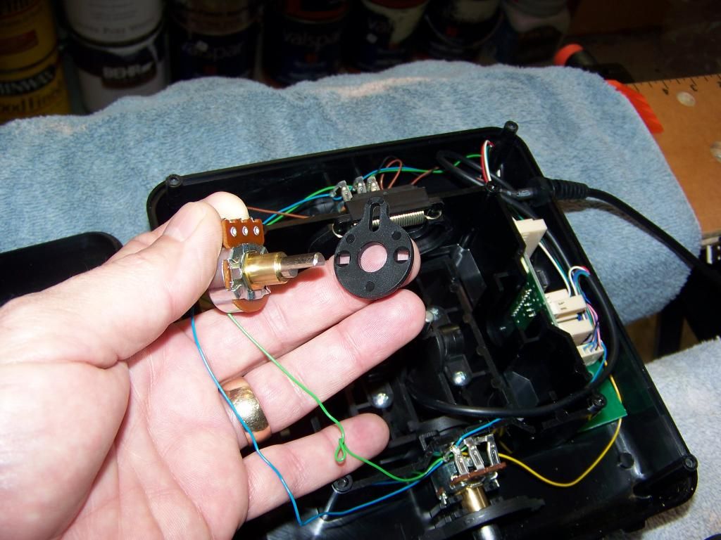
8) Remove the plastic piece from the Roll pot. IMPORTANT: note how the metal tabs on the pot engage the holes in this piece.
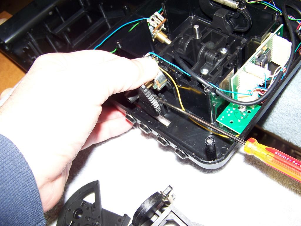
9) Next the Throttle pot assembly must be removed. Simply pry it up. Note how it faces away from the center and that the wires on it are a close fit compared to the other pots. IMPORTANT: there is a small bridge-like piece of plastic that fits into the cover side that holds this assembly in place when the cover is installed. IT MAY FALL OUT OF THE COVER. If it does, a small dab of RTV silicone will hold it in place for when the cover is reinstalled.
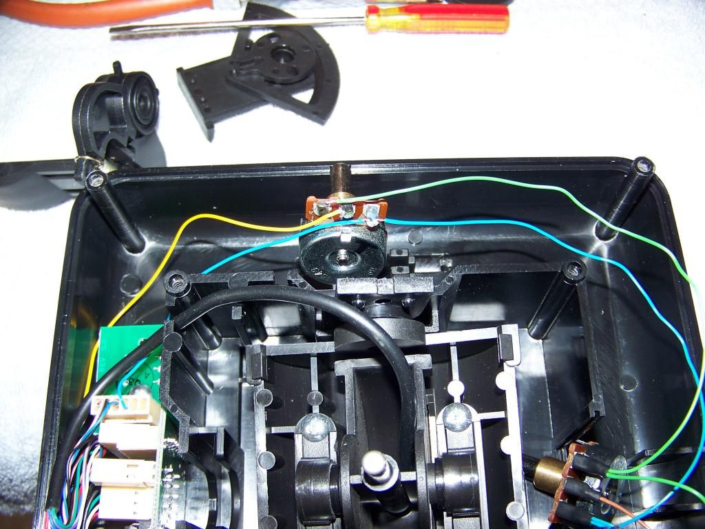
10) At this time the Pitch yoke assembly can be disassembled. It need only be raised enough to remove the Pitch pot and trim wheel assembly; therefore the stick handle need not be removed from the Pitch yoke assembly. Pull up on the Pitch yoke assembly evenly on both sides, just like the Roll yoke assembly, until it is raised as high as it can be. The Pitch pot will then be clear of the pot retainer in the housing.
11) With the Pitch yoke in the raised position, pull the Pitch pot and plastic piece out of the Pitch trim wheel assembly. Leave the Pitch trim wheel assembly on the Pitch yoke.
12) Remove the plastic piece from the Pitch pot, again noting how the metal tabs engage the plastic piece, for later reassembly.
13) IMPORTANT: at this point, make a diagram of the wire connections on all of the pots, laid out exactly the way they're installed in the joystick.
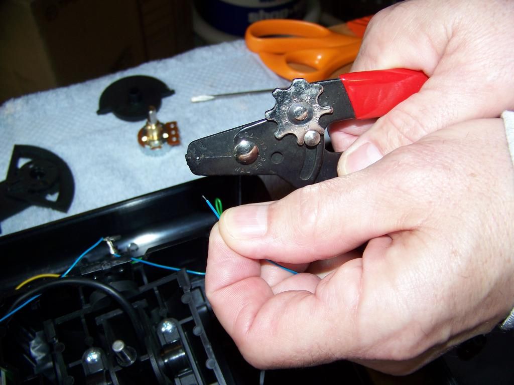
14) Optional: If you choose to ensure extreme reliability of the stick in the future, you may elect to make all solder connections. Therefore if you choose to do so, cut all of the crimped-on connectors off of the wires.
15) Strip all of the wires about 1/8 inch (the insulation is likely to melt back a bit more during soldering). Use an adjustable stripper set exactly for the tiny wire size, so as not to lose ANY strands. Then flux, and tin each wire, and form into small hooks.
15) Soldering 2 wires on a terminal. Heat shrink insulation, if used, must be placed over all wires before soldering. Apply flux to pot terminals and solder wires in place.
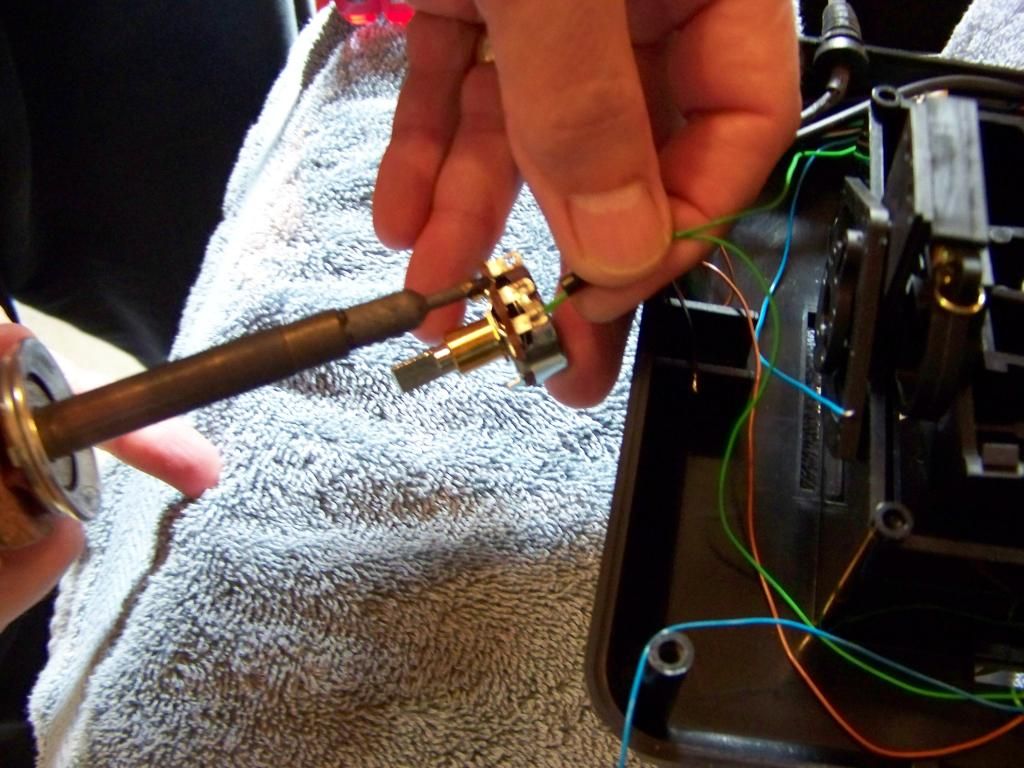
16) A new replacement pot with all wires soldered in place and heat shrink insulation installed with heat gun. (get a real heat gun, a hair dryer won't work; then beware of overheating!).
17) A view of the Throttle pot with properly soldered connections. The back of this pot is very near the Pitch yoke bearing, therefore the wires should be connected with the sideways orientation depicted; no heat shrink installation is possible here. Instead, bend the pot terminals as shown with one down, one straight, and one up, so that each connection is guaranteed not to contact any of the others. It should now fit into it's bearing easily without any interference.
18) The pot assemblies should be reinstalled in the following order: first Pitch, then Throttle, then Roll. Remember that on the Pitch and Roll yokes, the ROUND part of the end bearing must face DOWN. Then push both sides evenly until they are FULLY inserted. When installing the Roll yoke, ENSURE that the slot on the underside of the yoke is engaged with the metal rod on the bottom of the stick assembly.
19) The fully reassembled unit with soldered-in pots, with some small tie-wraps on the wires to hold things in place, but still free to move. Remember that the trim wheels should be free to rotate the pot assemblies without any wires pulling excessively. Make sure ALL of the wires are free and clear of the housing sides; then reinstall the bottom cover, making sure that the small plastic bridge piece is installed which holds the Throttle pot down. After installing all 8 screws, reinstall the 4 silicone feet (they should still stick just fine).
You're done!!
Information for procuring the HP-100A potentiometers:
CH PRODUCTS
970 Park Center Drive
Vista, CA 92081
Ph#: 760-598-2518
Fax#: 760-598-2524
Email: jsoucy@chproducts.com
www.chproducts.com
S!
1) It is optional but you can tape some blocks of some material to the top side of the stick (I used Styrofoam) in order to protect the trim wheels and yoke parts while the stick is upside-down.
2) There are 8 screws holding the bottom cover on that must be removed. Warning: removing these screws VOIDS any warranty that may still be in effect for your joystick. Remove the 4 in the center of the stick, one of which is under the "void warranty" sticker. Then carefully peel off the 4 silicone feet of the joystick to access the other 4, set the feet aside in a clean location for later re-installation, and remove the last 4 screws.
3) The open view. Pitch (Y) pot on the left, Roll (X) pot on the bottom, Throttle pot on the right. Note the chintzy "Sta-Con" type connectors on all the pots as original equipment. A couple of these were extremely loose on my unit, with one being on the left-most connection of the Roll pot. I suspect it was the problem, since testing of the original pots showed no discernable problem.
4) Lift the entire Roll yoke assembly straight up by lifting on both sides simultaneously. It is a friction fit. Note how the rod on the bottom of the stick unit engages the slot on the underside of the yoke. Also note that the front bearing slides into it's slot with the ROUND SIDE DOWN.
5) The trim wheel comes out with it.
6) Pull the Roll pot and trim wheel assembly out of the end of the Roll yoke.
7) Pull the pot assembly off of the trim wheel unit. Note how the slot on the pot assembly fits into the trim wheel unit. It is not necessary to disassemble the trim wheel unit any further.
8) Remove the plastic piece from the Roll pot. IMPORTANT: note how the metal tabs on the pot engage the holes in this piece.
9) Next the Throttle pot assembly must be removed. Simply pry it up. Note how it faces away from the center and that the wires on it are a close fit compared to the other pots. IMPORTANT: there is a small bridge-like piece of plastic that fits into the cover side that holds this assembly in place when the cover is installed. IT MAY FALL OUT OF THE COVER. If it does, a small dab of RTV silicone will hold it in place for when the cover is reinstalled.
10) At this time the Pitch yoke assembly can be disassembled. It need only be raised enough to remove the Pitch pot and trim wheel assembly; therefore the stick handle need not be removed from the Pitch yoke assembly. Pull up on the Pitch yoke assembly evenly on both sides, just like the Roll yoke assembly, until it is raised as high as it can be. The Pitch pot will then be clear of the pot retainer in the housing.
11) With the Pitch yoke in the raised position, pull the Pitch pot and plastic piece out of the Pitch trim wheel assembly. Leave the Pitch trim wheel assembly on the Pitch yoke.
12) Remove the plastic piece from the Pitch pot, again noting how the metal tabs engage the plastic piece, for later reassembly.
13) IMPORTANT: at this point, make a diagram of the wire connections on all of the pots, laid out exactly the way they're installed in the joystick.
14) Optional: If you choose to ensure extreme reliability of the stick in the future, you may elect to make all solder connections. Therefore if you choose to do so, cut all of the crimped-on connectors off of the wires.
15) Strip all of the wires about 1/8 inch (the insulation is likely to melt back a bit more during soldering). Use an adjustable stripper set exactly for the tiny wire size, so as not to lose ANY strands. Then flux, and tin each wire, and form into small hooks.
15) Soldering 2 wires on a terminal. Heat shrink insulation, if used, must be placed over all wires before soldering. Apply flux to pot terminals and solder wires in place.
16) A new replacement pot with all wires soldered in place and heat shrink insulation installed with heat gun. (get a real heat gun, a hair dryer won't work; then beware of overheating!).
17) A view of the Throttle pot with properly soldered connections. The back of this pot is very near the Pitch yoke bearing, therefore the wires should be connected with the sideways orientation depicted; no heat shrink installation is possible here. Instead, bend the pot terminals as shown with one down, one straight, and one up, so that each connection is guaranteed not to contact any of the others. It should now fit into it's bearing easily without any interference.
18) The pot assemblies should be reinstalled in the following order: first Pitch, then Throttle, then Roll. Remember that on the Pitch and Roll yokes, the ROUND part of the end bearing must face DOWN. Then push both sides evenly until they are FULLY inserted. When installing the Roll yoke, ENSURE that the slot on the underside of the yoke is engaged with the metal rod on the bottom of the stick assembly.
19) The fully reassembled unit with soldered-in pots, with some small tie-wraps on the wires to hold things in place, but still free to move. Remember that the trim wheels should be free to rotate the pot assemblies without any wires pulling excessively. Make sure ALL of the wires are free and clear of the housing sides; then reinstall the bottom cover, making sure that the small plastic bridge piece is installed which holds the Throttle pot down. After installing all 8 screws, reinstall the 4 silicone feet (they should still stick just fine).
You're done!!
Information for procuring the HP-100A potentiometers:
CH PRODUCTS
970 Park Center Drive
Vista, CA 92081
Ph#: 760-598-2518
Fax#: 760-598-2524
Email: jsoucy@chproducts.com
www.chproducts.com
S!